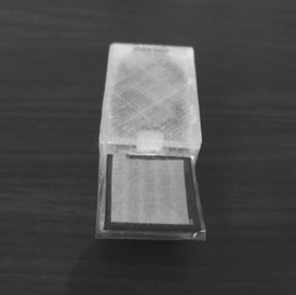
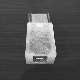
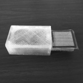
Flexi-pinch is a force-sensing system that is capable of detecting very low forces and could prove to be a useful tool for assessing strength. Flexi-pinch was designed for allied health practitioners to obtain valid, sensitive and dynamic force readings. The proposed system could be used across many different practice settings and has the potential to be used in areas such as neurological rehabilitation and workplace rehabilitation.
Approximate Time to Build + Test: 1 hour
Approximate Cost: Under USD$100
Difficulty: Easy - Moderate
Approximate Cost: Under USD$100
Difficulty: Easy - Moderate
IMPORTANT
This how-to guide shows a very simple example of a load cell system. You will be using tools that have the potential to start fires or cause burns (soldering irons), and potentially asking people to contract their muscles as hard as they can which could injure them or cause damage to the testing apparatus. We take no responsibility for any issues that arise from you using anything from this website.
* Disclaimer - No one involved in this website has any commercial or other interests in any of the companies or products used or discussed on this site.
EQUIPMENT
To build a force sensor like the one pictured above, you will need:
3D Printer Access
Access to the 3D print models for the sensor is available using the link below. Then all you need is a 3D printer. The model used in this study was a Lulzbot Taz 6 with ColorFabb Ngen plastic.
Data Acquisition System
There are many options, in this project we're using a SAMD21 Mini Arduino compatible microcontroller. Make sure to get a micro USB cable for it.
Wiring
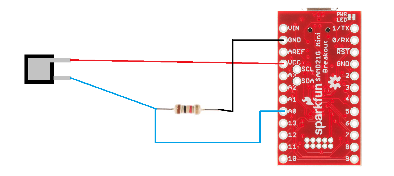
The circuit is very simple, and consists of just a single resistor, the fabric sensor and the Arduino. You can see how these are connected in the video, or just refer to the circuit diagram below.
Hot Glue Gun + Glue Stick/s
I like to use it on the finished circuit board to add extra strength to the connections and also prevent short circuits. You can get these from most electronics components or hardware stores, as well as craft stores. They are typically very cheap.
Plastic Glue
You might be able to use standard super glue, but plastic glue comes in very handy for attaching 3D printed parts together so is worth the investment.
Soldering Iron + Solder
Soldering these parts is very easy, if you have any doubts watch the videos on this page and look at some Youtube clips to see how it is done. For the iron make sure you buy one that fits your power supply - different countries have different wall sockets and voltages and it is always best to NOT use an adapter. I also strongly recommend having at least two soldering "third hands", preferably three, and keep the soldering iron in one that you don't use for the clamping. Otherwise you will inadvertently go to move the clamped piece by grabbing the spiral while holding the iron and burn yourself. Trust me, I have the burnt thumbs to prove it.
Wire Strippers
Your choice, the T-rex style ones work quite well. Otherwise these pliers-type ones from Sparkfun should be good.
Flush Cutters
These are great for snipping off bits of wire after you have finished soldering to make a smooth finish.
Pressure-sensitive Fabric
We've used this one from Eeontex.
Silver Conductive Fabric
There are many options for conductive fabric, this one is also from Eeontex and should work well.
Heat Shrink
Essential for work where there is electrical current, this stops short circuits from happening and destroying your sensors. Buying a packet of multiple size heat shrink is well worth it.
Brass Connectors
One of the trickier parts is connecting the conductive fabric to the wires - to do this we've used female spade connectors that you crimp onto both the wire and the fabric.
Plastic Contact
This is the material you use to cover school books - and works well for fusing the different fabrics together.
INSTRUCTIONS
Circuit Diagram
As you can see there's not much to the circuit:
The video below shows how to build the force sensing system, from start to finish!
Step 1: Prepare the Fabric
Using the template provided (Fabric Sensor Print Guide, see below), cut the black pressure-sensitive fabric into one 20mm x 20mm square. Using the template provided, cut the silver conductive fabric into one 18mm x 18 mm square with a tab off to one side that has a width of 3mm. Using the template provided, cut the plastic contact into two 24mm x 24mm squares.
Step 2: Stick the Fabric Together
Using two squares of plastic contact, stick the silver conductive fabric to alternate sides of the black pressure-sensitive fabric, making sure that there is an even border of black around the silver, and that the silver tabs don’t touch each other, but face the same way. Trim the excess contact.
Step 3: Prepare the Wires
Cut three pieces of electrical wire about 5 cm long - we use one red, one black and one blue. Use the wire strippers to expose wire at both ends of each wire. Solder the red one to VCC, the black one to GND and the blue one to A0. Also trim the wires on either side of the resistor to about 1cm long, to make sure it is a suitable length to work with when attaching the pressure sensor to the Arduino. Cut a suitable length of heat shrink and fit it onto the black wire before attaching anything to it.
Step 4: Prepare the Resistor
Attach the black wire to the resistor by twisting them together, and then soldering them together to secure it. You can use clamps (e.g. alligator clips) to make this job easier and safer. Move the heat shrink over the joint, and use the top end of the solder to shrink it in place and secure the joint. Make sure to cover all exposed wire on that side of the resistor.
Step 5: Attach Resistor/Arduino to the Pressure Sensor
Cut a suitable length (2cm) of a wider diameter heat shrink and put it onto the open wire of the resistor before attaching it to the pressure sensor. Place one of the tabs of the pressure sensor, the open wire of the resistor and the blue wire into the connector and clamp it shut using pliers. Solder this joint to make it stronger, and then move the heat shrink over the joint and shrink it to secure it. Use clamps (e.g. alligator clips) to make this easier. Solder this joint and move the heat shrink over the joint, shrink tightly to secure it. Repeat this crimping step to connect the red wire to the other tab of the pressure sensor.
Step 6: Attach Arduino to the 3D Printed Model
Squeeze a drop of glue (about the size of a pea) from the glue gun into the cavity of the 3D printed model. Place the Arduino into the box with the tab on the side of the grip and the USB port facing out of the box, and hold down for approximately 30 seconds.
Step 7: Attach Pressure-Sensor to the 3D Printed Model
Using plastic glue, stick the pressure sensor down onto the grip and hold down for approximately 30 seconds.
Step 8: Ensure Attachments are Fixed to the 3D Printed Model
Attach the tabs and wires neatly to the Arduino using a glue gun. Be aware of fibres coming off the conductive fabric, these can’t touch either as they are still conductive and will cause the board to short circuit.
The following two files are for the print guide, which has the templates you can use for cutting the fabric and contact, and also the 3D model for the flexi-pinch.
| Fabric Sensor Print Guide | |
| File Size: | 56 kb |
| File Type: | docx |
| flexi-pinch_model.stl | |
| File Size: | 7 kb |
| File Type: | stl |
LOAD CELL
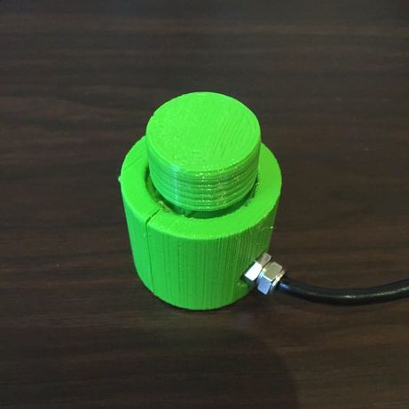
The best method for assessing strength is typically a load cell, as they can be very sensitive and reliable. Please see our page, "Building a Load Cell System" to find information about building your own system and how it can be used with custom software to perform calibration and data collection. The load cell example on this page uses the exact same circuit and software as is outlined on that page, but incorporates this button-type load cell instead of a S-type load cell. It also has a 3D printed shell to aid grip, and a printed cap for comfort. The 3D print model below is very simple, with the load cell being inserted inside it (make sure to put it inside the shell BEFORE soldering it to the amplifier board). We've then used a simple bolt as the "piston", with the cap on top of the bolt. Choose a bolt that fits inside the shaft snugly, and that has a flat head for you to put the cap on. If you like you can glue or friction weld the cap onto the bolt for a more permanent setup.
The following file is the 3D print model for the button load cell case.
| load_cell_for_pinch.stl | |
| File Size: | 42 kb |
| File Type: | stl |
Flexi-pinch Model by Ross36 on Sketchfab
CONTRIBUTORS
|
Claudia Cutler is an occupational therapy student who is currently completing her Honours research project examining ways to assess hand function. She is also working as an Allied Health Assistant at the Sunshine Coast University Hospital.
|
Ross Clark is a National Health and Medical Research Council RD Wright Biomedical Fellow at the University of the Sunshine Coast. He created this site and is the principal developer of the software, hardware and visualisation systems used.
|
Anita Hamilton is an occupational therapy educator at University of the Sunshine Coast. She has been enjoying working with Ross Clark using his custom software, hardware and visualisation systems to examine new ways of assessing hand function, with the goal of finding ways to assess pinch and grip force with everyday objects.
|
