Why use a LIDAR to assess gait?
- Very quick to set up
- Simple to use
- Precise, valid measurements over user defined intervals as small as 0.5m
- No wearable sensors or markers means no contamination issues in clinical settings
Traditional gait speed assessments typically consist of measuring how long it takes someone to walk a set distance using a stopwatch. This is not a bad way of measuring gait, but has a number of limitations including needing a long distance to overcome manual timing measurement error. Other methods include using timing gates such as photoelectric single and dual beam systems, but these can be difficult to use quickly as they need to be placed at set distances from each other and only provide the time it takes to go between 2 gates. If you are interested in other factors such as acceleration, maximal speed, multiple distance intervals etc. this is not readily achievable with timing gates. A LIDAR based system allows for the continuous acquisition of distance data, which overcomes the need to measure the distance between timing gates or set markings on the floor. It also minimal manual error - the only potential error is poor alignment of the LIDAR with the direction of gait.
Approximate Cost: Under USD$250
Approximate Time to Build and Test: Under 1 hour (if software already installed)
IMPORTANT
This how-to guide shows a very simple example of a LIDAR based gait assessment system. You will be using tools that have the potential to start fires or cause burns (soldering irons), and using lasers that can cause eye damage if used improperly. We take no responsibility for any issues that arise from you using anything from this website.
* Disclaimer - No one involved in this website has any commercial or other interests in any of the companies or products used or discussed on this site.
A very simple but accurate LIDAR system for assessing gait
The following hookup guide takes you through a very simple LIDAR system that also includes a computer controlled laser pointer to align the LIDAR with the direction of gait. DO NOT pull apart the laser or LIDAR, and do not stare directly into them for extended periods. Make sure to check the safety guidelines for the LIDAR and laser you use before using them.
SELECTING THE HARDWARE
LIDAR: For this guide we are using the Garmin LIDAR-Lite V3. It was chosen because of its low cost and characteristics particularly suited to assessing gait. These include a narrow focal beam, range to 40m and high speed data acquisition (up to 650Hz). It can be purchased from a range of online suppliers.
ARDUINO MEGA: The Mega is overkill for this project, and results in the enclosure being much larger than necessary. We use it because it is a great all-round Arduino and is used in other projects. You can replace it with an Arduino Uno or Pro Micro if you want to save size and/or cost. You can save money using off-brand models but I recommend using the original as they are much less likely to have issues with connection.
1 x 1000 Ohm RESISTOR: The resistor is essential for triggering the PWM that we are using in this guide.
LASER POINTER DIODE: These are very low cost and widely available online, for this example a Duinotech XC4490 was used but most diodes with a 5V input should work well. A quick google search for Arduino compatible laser pointer diode will show many options. The exact same model used here is rebranded in many ways and should be a direct swap.
BREAKAWAY HEADERS: These are simply pins that you will solder the LIDAR wires to, allowing them to be directly connected to the Arduino.
CONNECTING IT TOGETHER
For this guide it has been made as simple as possible, with only three soldering connections and a solderless breadboard used instead of a circuit board. It would likely be much more reliable long term if you solder the connections on a circuit board, or at least use hot glue on all of the connections to stop the wires from disconnecting.
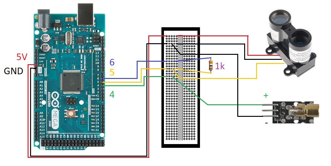
The following image shows the circuit diagram:
The following image shows the circuit diagram:
The only soldering was the three wires (black, red, yellow) of the LIDAR to the breakaway headers. The laser pointer diode was connected using a combination of female (to the laser pointer) and male (from the female cable to the breadboard) breadboard header cables. The circuit diagram above doesn't include the capacitor shown in the video below - but it doesn't hurt to add it to smooth out any voltage fluctuations. Both the capacitor and the resistor are simply plugged directly into the breadboard.
A video of the electrical connections is shown here:
A video of the electrical connections is shown here:
SOFTWARE
You can install the Arduino code onto the Mega using this link
* If you are unsure how to use this refer to the how-to video for the load cell installation
* If you are unsure how to use this refer to the how-to video for the load cell installation
The following software program allows you to use the data being output from the Arduino to create a simple timing gate. You can set it to as small or large as you want, the default is to measure the gait speed between 3m and 2m away from the LIDAR and convert this to m/s.
| LIDAR Interface Software | |
| File Size: | 1556 kb |
| File Type: | exe |
* Make sure you have installed the overhead software and restarted your computer before running the interface program. You can download it from this link (caution - around 500MB)
Building an enclosure
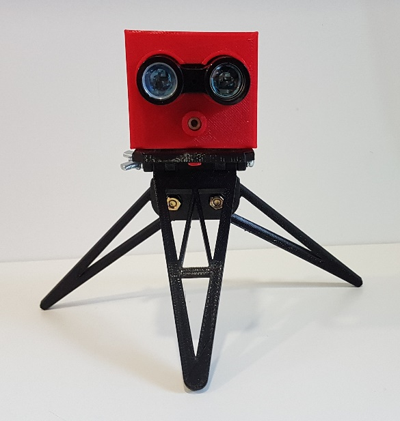
You can use the LIDAR system without a cover, but it will be much easier to setup and use with one. You can download and use the 3D print model below, or import it into a program like Tinkercad and modify it to suit your needs. A couple of key points:
1. Ensure the LIDAR is mounted flat on the cover - even a small tilt will have a very large impact on your results.
2. Mounting the laser diode properly is important to ensure alignment of the LIDAR with the direction of movement. The model below may need to be modified to suit your diode - either reshape the 3D model or drill out the hole in the cover.
3. Obviously this is not waterproof - so please don't use it in the rain!
The following video shows how the system is embedded in the 3D printed enclosure, and how it is then sealed using plastic glue.
ADVANCED SETUP AND DESIGN
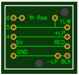
If you want a more permanent solution you can use a printed circuit board (PCB) such as this one to replace the breadboard. It is possible to order these designs online and shipped to your door very cheaply, and you can even add the resistor to the board design and have the final product shipped, with the only requirement being soldering up the wires. Click the image of the PCB to go to EasyEDA, a free web-based program for designing PCBs. You may have to modify the settings depending on which company you use to create it.
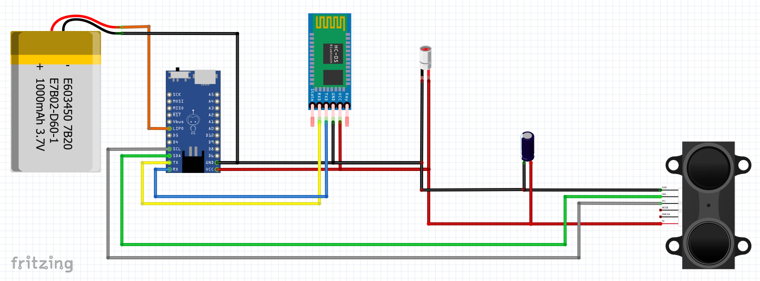
To make the system wireless is easy, simply connect a Bluetooth module (non-BLE) to the RX and TX pins (make sure to connect RX to TX and TX to RX), in addition to connecting the Ground and Power Supply pins. Then connect either a battery supply or power pack to the Arduino, preferably one with a switch. Then simply turn the power on, connect the Bluetooth module to your computer as standard and your computer should see it as a normal COM port. If not check the baud settings are compatible between the Bluetooth module and the Arduino program, if not just change the Arduino Baud value to match the Bluetooth module.
Here's an example of a wireless version that I have created (note - this will not work with the code above). It underpowers the LIDAR but I have never had any issues with it:


