Which Microcontroller?
The great thing about the potentiometer is that any microcontroller can read data from it. You can use the Teensy or Mega from other examples, or a simple Arduino Uno. An important point is that the analogue to digital (ADC) converter the microcontroller has in it will make a big difference. For this reason I recommend one with 12-bit ADC or higher, which will provide precision to <0.1 degrees. To make the system wireless I would recommend a small controller such as the Adafruit Trinket M0 series connected to a Bluetooth module.
The Potentiometer and its Shell
The 3D printed arms used for the potentiometer are shown in the image below. You can download the STL file ready for 3D printing by clicking the following "Download File" link.

| finger_goni.stl | |
| File Size: | 30 kb |
| File Type: | stl |
The rotary potentiometer itself was purchased from Sparkfun Electronics. Click this link to go to their website. Remove the nut from the threaded shaft, then slide the short 3D printed arm on to it. The small notch on the short arm goes onto the connector highlighted in the red circle in the image below.
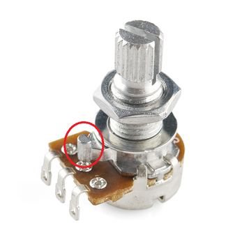
Connecting the Potentiometer to the Microcontroller
This is as simple as it gets - just connect the 5V pin from the Arduino to one of the outside connectors on the potentiometer, and the Gnd pin to the other outer connector. The order doesn't matter. Then connect the middle connector on the potentiometer to an Analog input. The example picture below shows it connected to A2 (i.e. Analog pin 2). The picture below is from the official Arduino site.
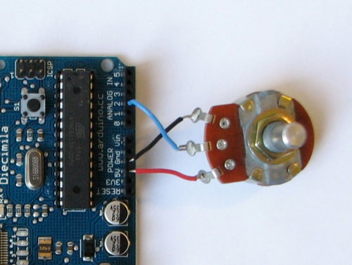
Once the potentiometer is connected to the Arduino, you can connect the Arduino to your computer and upload the following code via the Arduino software. Make sure the COM port is correct. Once it is uploaded, you can open Serial Monitor in Arduino to read the Potentiometer value. This can be easily calibrated into degrees using the calibration techniques described on this page.
| analogpotvalue.ino | |
| File Size: | 0 kb |
| File Type: | ino |