Approximate Time to Build and Test: Under 1 hour
Approximate Cost: Under USD$200
Difficulty: Easy for off-the-shelf scale, Moderate for custom system and software
If you use any aspects of this software for research purposes please reference the following article (link to reference export):
Cutler CR, Hamilton AL, Hough E, Baines CM, Clark RA, Open-source 3D printed sensors for hand strength assessment: Validation of low-cost load cell and fabric sensor-based systems, Australian Occupational Therapy Journal. 65 (2018) 412-9.
Cutler CR, Hamilton AL, Hough E, Baines CM, Clark RA, Open-source 3D printed sensors for hand strength assessment: Validation of low-cost load cell and fabric sensor-based systems, Australian Occupational Therapy Journal. 65 (2018) 412-9.
IMPORTANT This how-to guide shows a very simple example of a load cell system. You will be using tools that have the potential to start fires or cause burns (soldering irons), and potentially asking people to contract their muscles as hard as they can which could injure them or cause damage to the testing apparatus. We take no responsibility for any issues that arise from you using anything from this website. * Disclaimer - No one involved in this website has any commercial or other interests in any of the companies or products used or discussed on this site.
Why Use a Load Cell to Measure Strength?
There are many ways to assess a person’s strength, ranging from the "best left to the 1970's" (push against me and I'll give you a rating of 1 to 5) through to the very sophisticated (isokinetic dynamometry which uses a robot to control the speed of movement). Repetition maximum strength testing is a great way to do it, and consists of a person lifting the heaviest weight they can for the prescribed number of repetitions. For example, a 1 repetition maximum knee extension would mean the person has to lift the heaviest load they can for 1 repetition of this exercise. However, this is very time consuming and relies on the person running the test to estimate the strength of the person being tested and "guess" the loads to use for warming up and assessments. Isometric strength testing can be performed in a fraction of the time, and can be particularly beneficial and sensitive to change in weak populations as it is not limited to the weight increments available with gym equipment. For example, if someone post surgery can only perform a 5kg knee extension and the gym equipment only has 5kg increments they would have to double their strength to be able to lift the next possible load. In contrast, a well matched load cell can be sensitive to strength improvements of grams and therefore small but important changes won't be missed. You can buy load cell systems that are complete packages, and we have used these for a number of purposes. This page deals with building your own system and shows how it can be used with custom software to perform calibration and data collection.
The Easy System
Simply follow the directions BUT replace the load cell, arduino and computer with a simple crane scale. This will do all the work for you and provide you with a peak force value. This means all you do is purchase a "crane scale" (follow the recommended load cell guidelines with respect to maximum load etc.) and then follow the setup regarding the chain, straps etc.
Load Cell Hookup Guide - A Brief Intro!
This page is designed to show you how to build a load cell based strength testing device. It's quite simple, and all it takes is some very basic soldering and connecting a few wires together. The system is designed around the Sparkfun Electronics "Load Cell Amplifier" chip, which is a very low cost alternative to standard load cell amplifiers. You can find their "hookup" guide here. If you are intending to use different electronics than those discussed on this page it is strongly recommended that you read it. The purpose of this page is to make it as simple as possible for you to implement a system if you do not have much/any electronics or custom software programming experience. It's predominantly video based so you can see every single step.
SELECTING THE HARDWARE
Choosing a Load Cell
This is a very important step to ensure that you get the best possible data. As a rule of thumb:
- Estimate the highest conceivable load it would be subjected to in your testing, then add another 50%. This gives you a rough idea of the capacity of the load cell you should buy. For example, if you think the forces will be 120kg maximum, this would need a 180+kg load cell. A typical capacity is 200 or 250kg, so choose this one. Why not just get a 10 tonne load cell? The reason for this is because the error, sensitivity etc. of load cells is related to their capacity. Therefore a 250kg load cell will be much more sensitive to small changes in force than a 10 tonne load cell.
- Buy a load cell that suits the type of test you will be performing. S-type load cells are very common, and many of them can measure both compression and extension forces. This is the type we will be using in this example. Other versions such as button load cells are also very useful for certain tasks.
- Have a look at the specifications. The following is a typical table:
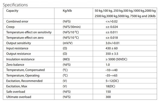
The combined error is a key aspect. This load cell is +0.02 as a % of full scale. Therefore a 100kg version would have +20 grams of error, whereas a 5000kg version would have +1kg of error. Creep refers to the amount of drift you will see in the data, load cells are known for drifting over time which means that they slowly move away from their starting value the longer they are turned on for. Again this is a % of full scale, so the lower capacity load cell would have less drift. Temperature also has an effect on the data, but many load cells or their amplifiers will be temperature compensated. Again, if you choose the right capacity of load cell you can minimise the effect of these factors.
You can often buy high quality load cells for a low cost on ebay or Amazon. If you find multiple load cells that fit your criteria, try and choose one that has the additional parts you might need to create the system you want. For this project we are going to be creating a knee extension strength testing device, and what we need is:
You can often buy high quality load cells for a low cost on ebay or Amazon. If you find multiple load cells that fit your criteria, try and choose one that has the additional parts you might need to create the system you want. For this project we are going to be creating a knee extension strength testing device, and what we need is:
Parts for an isometric knee extension strength testing device
CORE LOAD CELL COMPONENTS NEEDED
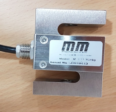
LOAD CELL: 1 x 250kg S-type. I have not linked to a specific model as it will be cheapest to buy one in your country instead of internationally. Once you have read the above "Choosing a Load Cell" section you should be able to select one from Amazon, Ebay etc. For this project I used a Meltrons MT501 S-type load cell rated at 250 kg. They are a New Zealand based company, and I found the load cell to be quite high quality. You could also use this one from Sparkfun.
AMPLIFIER: 1 x SparkFun Load Cell Amplifier - HX711. This is a great amplifier. It is limited in its out of the box sample rate to 10Hz, but can be easily converted to 80Hz by cutting the very thin metal connection between the two "RATE" tabs on the bottom of the chip. These two sampling options should allow you to perform the majority of assessments you want.
WIRING: Packet of jumper wire breadboard pins. Minimum of two jumper wires required, but I prefer to have a pack and use different colours for all wires.
DATA ACQUISITION SYSTEM: There are many options, in this project we're using an Arduino MEGA2560. Make sure to get a USB cable for it. If you are confident you could save a lot of money and use a pro micro 5V from Sparkfun, but you would need to do more soldering and it would not be as reusable as the MEGA2560.
TOOLS REQUIRED
SOLDERING IRON, STAND AND SOLDER: Soldering these parts is very easy, if you have any doubts watch the videos on this page and look at some Youtube clips to see how it is done. For the iron make sure you buy one that fits your power supply - different countries have different wall sockets and voltages and it is always best to NOT use an adapter. I also strongly recommend having at least 2 soldering "third hands", preferably 3, and keep the soldering iron in one that you don't use for the clamping. Otherwise you will inadvertently go to move the clamped piece by grabbing the spiral while holding the iron and burn yourself. Trust me, I have the burnt thumbs to prove it.
WIRE STRIPPERS: Your choice, the T-rex style ones work quite well. Otherwise these pliers-type ones from Sparkfun should be good.
FLUSH CUTTERS: These are great for snipping off bits of wire after you have finished soldering to make a smooth finish.
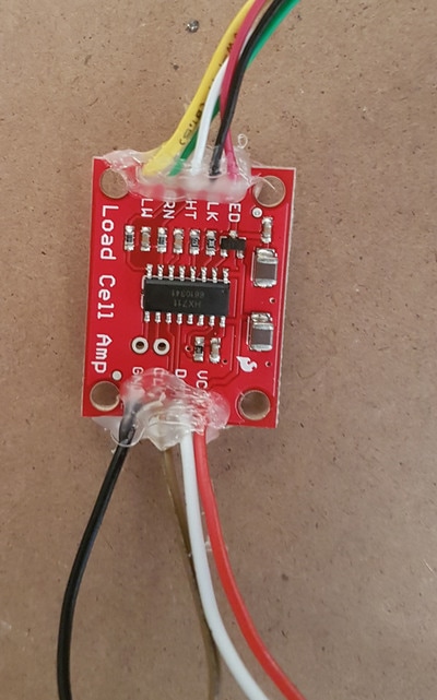
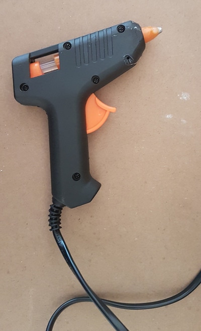
Optional - HOT GLUE GUN: I like to use it on the finished circuit board to add extra strength to the connections and also prevent short circuits. You can get these from most electronics components or hardware stores, as well as craft stores. They are typically very cheap.
KNEE EXTENSION DEVICE SPECIFIC PARTS
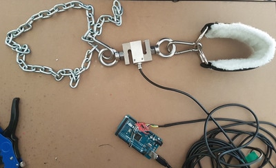
**Check the capacity of all of these parts and ensure that they exceed that of the load cell. You should be able to get all of these parts from a hardware store except the ankle strap, which gym equipment stores sell. Random pictures of these are shown at the bottom of the page.
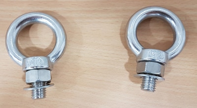
2 X EYE BOLTS: These bolt into the load cell and allow you to attach chain etc. to either end.
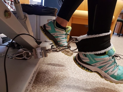
2 x CARABINER CLIPS: These are simple but strong clips that will connect your load cell to the chain and the ankle strap.
1 x 1m CHAIN: You can use other methods, but chain always works well.
1 x GYM ANKLE STRAP: This allows for the knee extension test to be performed comfortably.
LOAD CELL: 1 x 250kg S-type. I have not linked to a specific model as it will be cheapest to buy one in your country instead of internationally. Once you have read the above "Choosing a Load Cell" section you should be able to select one from Amazon, Ebay etc. For this project I used a Meltrons MT501 S-type load cell rated at 250 kg. They are a New Zealand based company, and I found the load cell to be quite high quality. You could also use this one from Sparkfun.
AMPLIFIER: 1 x SparkFun Load Cell Amplifier - HX711. This is a great amplifier. It is limited in its out of the box sample rate to 10Hz, but can be easily converted to 80Hz by cutting the very thin metal connection between the two "RATE" tabs on the bottom of the chip. These two sampling options should allow you to perform the majority of assessments you want.
WIRING: Packet of jumper wire breadboard pins. Minimum of two jumper wires required, but I prefer to have a pack and use different colours for all wires.
DATA ACQUISITION SYSTEM: There are many options, in this project we're using an Arduino MEGA2560. Make sure to get a USB cable for it. If you are confident you could save a lot of money and use a pro micro 5V from Sparkfun, but you would need to do more soldering and it would not be as reusable as the MEGA2560.
TOOLS REQUIRED
SOLDERING IRON, STAND AND SOLDER: Soldering these parts is very easy, if you have any doubts watch the videos on this page and look at some Youtube clips to see how it is done. For the iron make sure you buy one that fits your power supply - different countries have different wall sockets and voltages and it is always best to NOT use an adapter. I also strongly recommend having at least 2 soldering "third hands", preferably 3, and keep the soldering iron in one that you don't use for the clamping. Otherwise you will inadvertently go to move the clamped piece by grabbing the spiral while holding the iron and burn yourself. Trust me, I have the burnt thumbs to prove it.
WIRE STRIPPERS: Your choice, the T-rex style ones work quite well. Otherwise these pliers-type ones from Sparkfun should be good.
FLUSH CUTTERS: These are great for snipping off bits of wire after you have finished soldering to make a smooth finish.
Optional - HOT GLUE GUN: I like to use it on the finished circuit board to add extra strength to the connections and also prevent short circuits. You can get these from most electronics components or hardware stores, as well as craft stores. They are typically very cheap.
KNEE EXTENSION DEVICE SPECIFIC PARTS
**Check the capacity of all of these parts and ensure that they exceed that of the load cell. You should be able to get all of these parts from a hardware store except the ankle strap, which gym equipment stores sell. Random pictures of these are shown at the bottom of the page.
2 X EYE BOLTS: These bolt into the load cell and allow you to attach chain etc. to either end.
2 x CARABINER CLIPS: These are simple but strong clips that will connect your load cell to the chain and the ankle strap.
1 x 1m CHAIN: You can use other methods, but chain always works well.
1 x GYM ANKLE STRAP: This allows for the knee extension test to be performed comfortably.
Connecting everything together
A picture tells a thousand words:
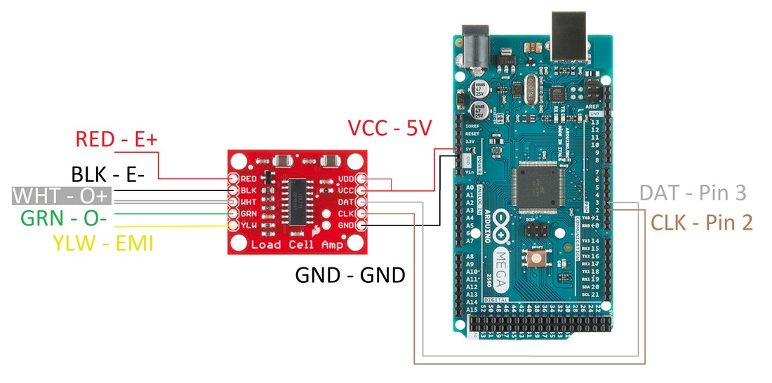
The following video shows the entire process for connecting the load cell to the amplifier board, then attaching the jumper wires to the amplifier board and connecting it to the Arduino MEGA2560.
*****NOTE - the chip in the video does not have the VDD connection - simply connect VDD to the VCC using either a piece of wire between them or just link the solder between the two eyelets.
*****NOTE - the chip in the video does not have the VDD connection - simply connect VDD to the VCC using either a piece of wire between them or just link the solder between the two eyelets.
GETTING THE DATA
Which data acquisition system should I use?
For data acquisition (DAQ) you can choose any number of systems, including:
- Your current DAQ system - you may already have a system such as a PowerLab or National Instrument hardware.
- A new dedicated DAQ system - the systems from National Instruments range from reasonably low cost through to very expensive. You typically get what you pay for to some extent, but for these purposes a low cost system should be more than enough.
- A microcontroller with analogue to digitial conversion capability - this can include systems such as the Raspberry Pi (with additional inputs), Lattepanda or one of my favourites the Arduino
Setting up our choice for this project: Arduino MEGA2560
The Arduino Mega2560 is a quite powerful yet simple to use microcontroller with numerous input and output possibilities. You could use lower-cost Arduinos for this project (eg. Uno) and they would be just as good. However, I often use the Mega because it has a few advantages such as more analog input pins and multiple serial ports. This makes it much more flexible if you want to use it for other projects.
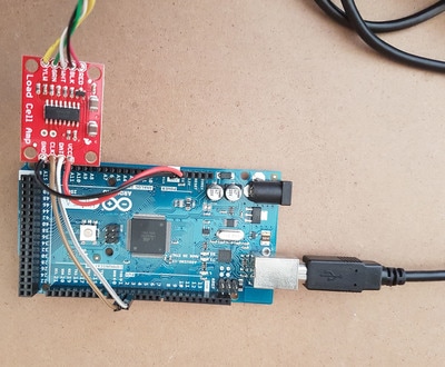
Connecting your load cell to the MEGA2560
Connection is very simple. Just connect the pin from:
- VCC (think of it as the voltage to the chip) into 5V (5 Volts power supply from the Arduino). This powers the amplifier, and is the same as + on a battery
- DAT (this is the data being transferred) into DIGITAL PIN 3. This receives the data.
- CLK (this is a clock timer the amplifier needs) into DIGITAL PIN 2.
- GND (short for ground) into GND. This is the same as - on a battery. Don't mix this up with the VCC pin!
Uploading the program and seeing some load cell data!
The video demonstrates the original Arduino Web Editor workflow. Use the downloadable sketch below for the desktop Arduino IDE; an online editor account is not required for that route.
Here's the code:
Arduino sketch
Download the original sketch and HX711 library, then follow the installation steps below.
View Arduino sketch
/*
QUICK README:
The following code is a modification done by Ross Clark of the code created by Nathan Seidle from Sparkfun Electronics. If you meet him you
must buy him a beer under the rules of the Beerware licence.
This example code also uses bogde's excellent library for the HX711: https://github.com/bogde/HX711
bogde's library is released under a GNU GENERAL PUBLIC LICENSE

If this version does not work you can download the files from the https://www.rehabtools.org  website and open in Arduino on your computer.

*/

#include "HX711.h"

// This assumes the following connections have been made
// Amplifier Board DAT = Arduino digital pin 3
// Amplifier Board CLK = Arduino digital pin 2

HX711 scale(3, 2);    // parameter "gain" is ommited; the default value 128 is used by the library
float force = 0;
#define calibration_factor -7050.0

// Generally, you should use "unsigned long" for variables that hold time
// The value can quickly become too large for an integer to store - not in this case but its good practice
unsigned long previousMillis = 0;        // will store last time the serial output was updated

// constants won't change :
const long interval = 1;           // interval at which to check for changes in the load cell data (milliseconds). 1 is fine


void setup() {
  Serial.begin(57600);
  scale.set_scale(calibration_factor); //Calibration factor (defined above) is very important for the accuracy of your data.
  //The number in this code is arbitrary and will not be directly applicable to your load cell, but will likley put you in the ballpark
  //You can then experiment with the Sparkfun code or the additional software from my site (rehabtools.org)
  scale.tare();  //Zero the load cell - this is important to remove factors such as drift or when starting with something on the load cell
  // you don't want to include in the weight.

  }

void loop() {
  force =  scale.get_units()*0.453592; //This multiples the original value by 0.454 to convert from lbs to kg.

  //The following section is a very good piece of code to use when collecting data. It waits for a set interval (set above) then runs the subsequent code.
  unsigned long currentMillis = millis();
  if (currentMillis - previousMillis >= interval) {
      previousMillis = currentMillis;
   Serial.println(force); //This prints the force value from the load cell to the serial port. You can then use this data for your own programs
   // or extract it using the examples on my site (rehabtools.org).
  }
}
Install the sketch
Arduino IDE installation instructions ↗
- Open the downloaded
load_cell_website_v2.inosketch in the Arduino IDE. - Install the supplied HX711 library. This sketch uses the original library bundled with this guide.
- Select your board and serial port, then upload the sketch.
- Check the serial output before moving on to calibration.
Calibration and data collection
The original Windows program provides calibration and data collection. The video demonstrates its workflow.
Open original Windows software download ↗** Note - This code is for Windows only. You may be able to run it on Mac computers using a Windows emulator, however I cannot guarantee it. It is an example only. The video shows how to install it on a Windows 10 computer, earlier versions of Windows will be slightly different however the steps will for the most part be the same.
** Second Note: I can't believe I called it "The Google". I make fun of my mother in law for that....
** Second Note: I can't believe I called it "The Google". I make fun of my mother in law for that....
Calibrating the Load Cell
The best method for calibrating the load cell is to have it in the position you are testing in and apply a series of known loads to it. Pausing for at least a few seconds before setting the load in the program will allow the value to stabilise. The best known loads are weights that themselves have been calibrated, and if you are associated with a university or hospital that has strength testing devices you may already have them. Other options are to get gym weights and either use the values written on them (they are often out by more than you'd expect though) or put these on a high quality scale and then use this calibrated weight for each plate. Additionally, you can use something like a hand held dynamometer and push against the load cell to perform a calibration.
Creating a Testing Rig
There are many different ways load cells can be used to create strength testing systems, including pushing, pulling, multiple load cells to assess multiple body parts at once and different grip attachments connected to the load cell. The example in this project is a simple knee extension strength testing device which we set up on a plinth. Please be careful if replicating this, because if you connect the load cell to a weak plinth and ask the person to extend their knee they could collapse the plinth on themselves! It's simple - if you have any doubts at all don't use it.
The following video shows how the parts were put together to create it - there is no voiceover for this one as it is pretty simple:
The following video shows how the parts were put together to create it - there is no voiceover for this one as it is pretty simple:
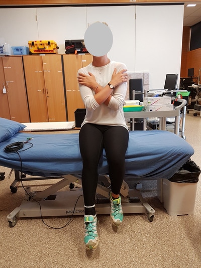
The next slideshow is a bunch of random pictures showing some close-ups of parts, things that weren't covered in the videos (eg. the hot glue gun) and someone performing the test (thanks Emma!).
View 8 original slides / images
CONTRIBUTORS

Ross Clark
Ross Clark is a National Health and Medical Research Council RD Wright Biomedical Fellow at the University of the Sunshine Coast. He created this site and is the principal developer of the software, hardware and visualisation systems used.
Funding received from: