IMPORTANT
This how-to guide shows a very simple example of an electromyography system designed to acquire muscle voltage recording and convert them into keyboard or mouse inputs. You will be using tools that have the potential to start fires or cause burns (soldering irons), and amplifiers that can cause serious health problems if used improperly. We take no responsibility for any issues that arise from you using anything from this website.
* Disclaimer - No one involved in this website has any commercial or other interests in any of the companies or products discussed on this site.
How do I build a Cheap EMG System?
Quite Easily!
The following example uses:
1. A Myoware muscle sensor chip
2. A Sparkfun Artemis Nano microcontroller - this is a fantastic device. It allows up to 14-bit analogue-to-digital conversion resolution and is very powerful. It has on-board Wi-Fi and Bluetooth Low Energy capability, however for this project Bluetooth Classic is the simplest method.
3. A lithium polymer battery - Choose one with over 500mAh capacity for safety reasons. For this project we are using a 600mAh battery with the dimensions 36mm long x 29mm wide x 5.5mm deep. Try and get one that is the same or narrower width as this is the limiting factor for fitting the 3D printed enclosure, slightly longer or higher is not an issue. This Adafruit one is a good example.
4. A JDY-31 Bluetooth Classic module. This is by far the simplest and cheapest Bluetooth Classic module I've ever used. Simply connect it up and it should work straight away. I have had trouble changing settings on it though, however for the purpose of this project or for general use that is of no concern. You can replace this with more conventional HC05/HC06 of BlueSMIRF type chips to get higher sampling rates or longer distances, however these are so cheap and easy therefore if you are new to Bluetooth I strongly recommend them.
The following example uses:
1. A Myoware muscle sensor chip
2. A Sparkfun Artemis Nano microcontroller - this is a fantastic device. It allows up to 14-bit analogue-to-digital conversion resolution and is very powerful. It has on-board Wi-Fi and Bluetooth Low Energy capability, however for this project Bluetooth Classic is the simplest method.
3. A lithium polymer battery - Choose one with over 500mAh capacity for safety reasons. For this project we are using a 600mAh battery with the dimensions 36mm long x 29mm wide x 5.5mm deep. Try and get one that is the same or narrower width as this is the limiting factor for fitting the 3D printed enclosure, slightly longer or higher is not an issue. This Adafruit one is a good example.
4. A JDY-31 Bluetooth Classic module. This is by far the simplest and cheapest Bluetooth Classic module I've ever used. Simply connect it up and it should work straight away. I have had trouble changing settings on it though, however for the purpose of this project or for general use that is of no concern. You can replace this with more conventional HC05/HC06 of BlueSMIRF type chips to get higher sampling rates or longer distances, however these are so cheap and easy therefore if you are new to Bluetooth I strongly recommend them.
Connecting it Together
The circuit is straightforward, just make sure to connect the TX pin from the Artemis to the RX pin on the JDY-31. Vice versa for the RX pin from the Artemis to the TX pin of the JDY-31. Use the 3.3V output from the Artemis to power the Myoware and Bluetooth. Two things you can do to improve the system are 1) Put a top mounted switch on the Artemis to allow it to be easily turned off and on, and 2) remove the Lipo JST connector and wire the battery directly to the + and - terminals to save space.
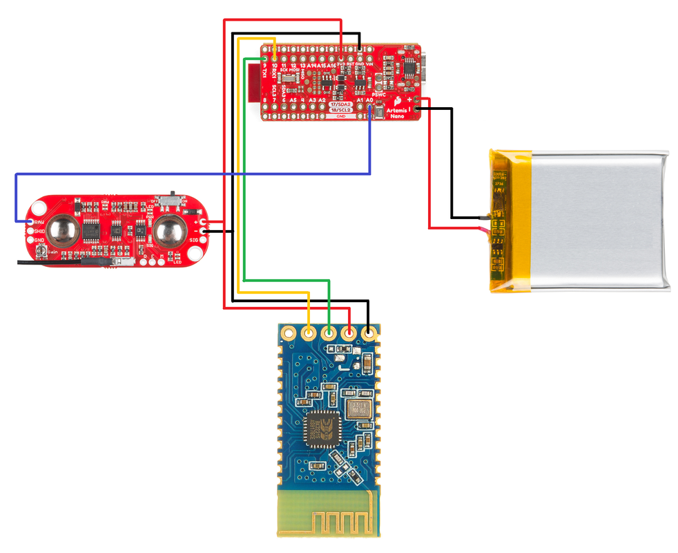
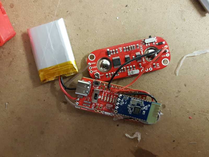
The EMG device connected up
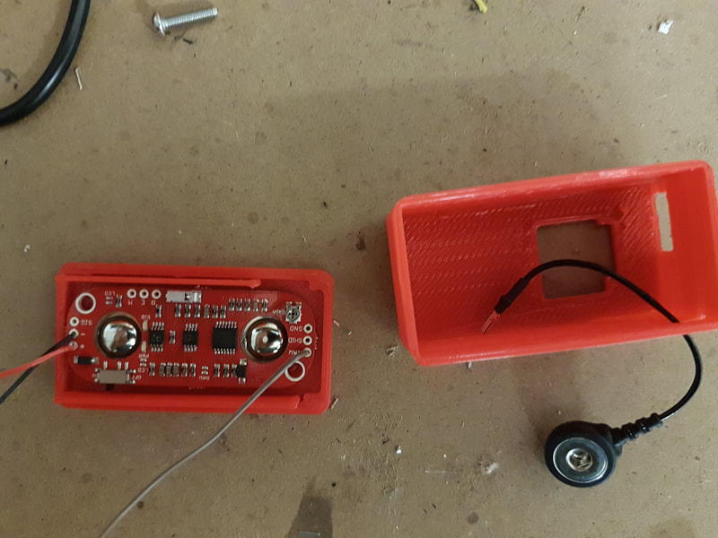
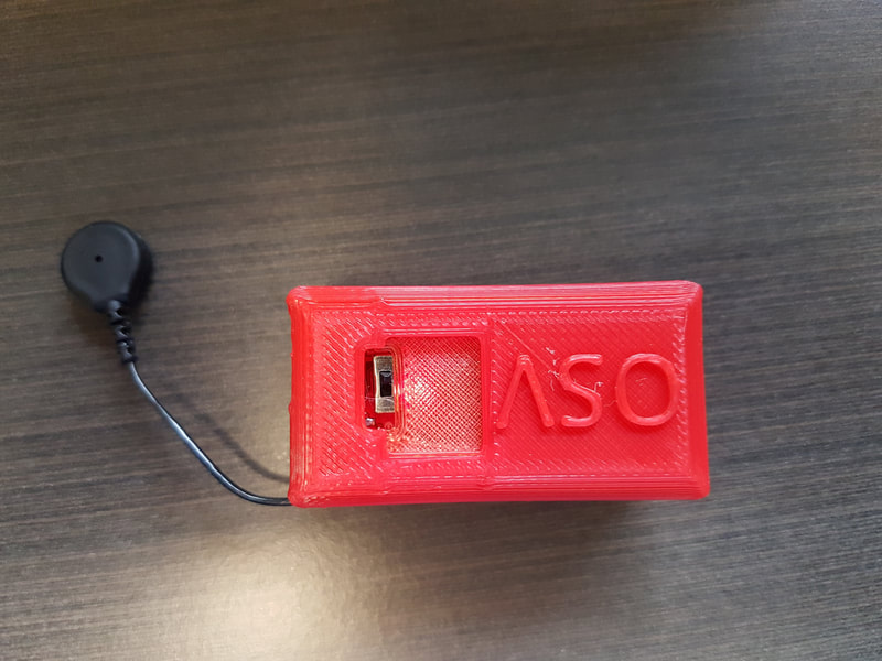
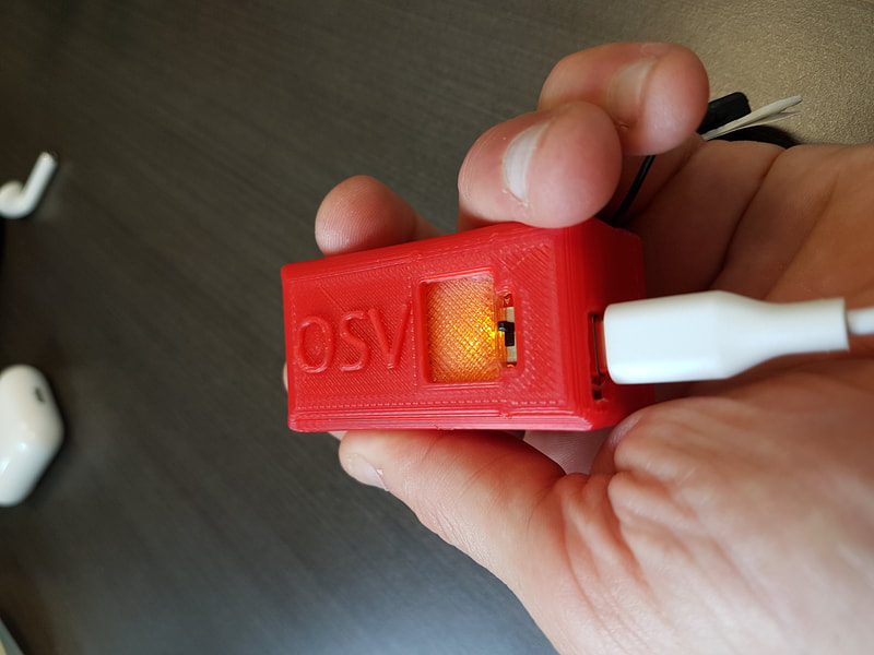
The pictures below show the system in various stages of the build.
The Enclosure
The 3D model shown below is printable and will enclose the system as shown in the various build images in the preceding images. If you print it as a single model it is a good idea to use transparent filament to allow you to see the charge circuit. The design was made like this so that the main body was not transparent, and only the top cover was. This was then simply glued into the main body using plastic glue prior to putting the electronics in the device. For the build it is best to put plastic glue on the baseplate (the one with the two large holes for the electrode connectors to sit in) and press the Myoware board to it in the correct position. This will fasten the EMG system in place, if it pops loose once the system is finalised then it is very hard to fix without breaking the enclosure. Once this is glued together you can then run some plastic glue along the outside top edge of the baseplate and then sandwich it together with the main body to enclose the system.
Microcontroller Code
The original sketch sent EMG readings through the JDY-31 Bluetooth Classic module. The sketch is not available in this archive, so the hardware description and Windows software alone are insufficient to reproduce the complete system.
The original microcontroller sketch could not be recovered. This page preserves the hardware and study documentation; it is not a complete software build package.
Computer Code
Click this link to download the software to collect the EMG data on a Windows PC and use it to simulate either a left mouse button click or pressing a key on the keyboard. Download the zipped file, then double click it and extract all of the files and folders. Double click the setup.exe file to install the software. You will need to restart your computer before the program will work.
View 4 original slides / images